

Table of Contents
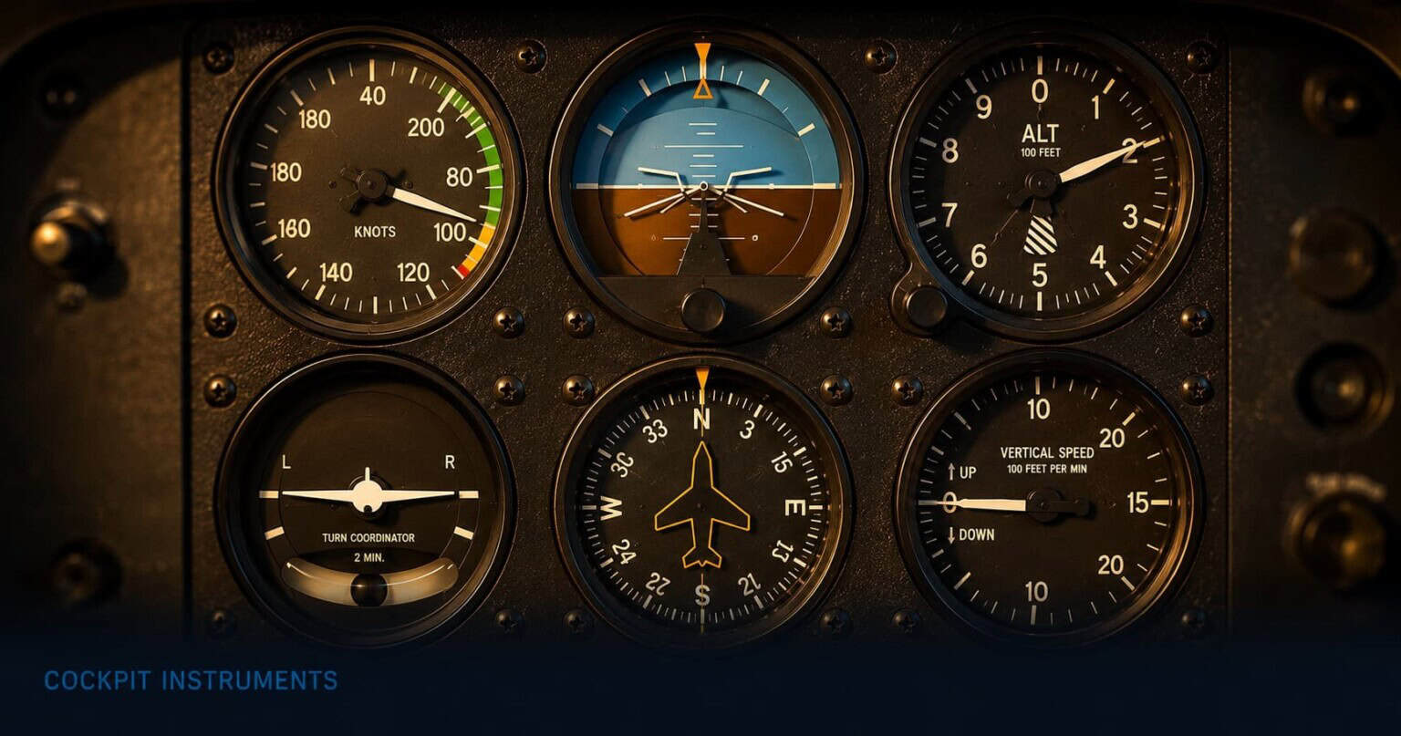
Look at the instrument panel of any small training aircraft and your eye will eventually settle on a cluster of six round gauges arranged near the centre. They are not random. They are not decorative. Each one answers a specific question that a pilot in flight needs answered continuously: how fast, how high, which way, whether level, whether climbing, whether the turn is balanced. Together, these six instruments give a complete picture of what the aircraft is doing in the air. Pilots call this cluster the six-pack.
The six-pack has been the foundation of instrument flying for nearly ninety years. The British Royal Air Force standardised the arrangement in 1937 and incorporated it into every aircraft built to official specification from 1938. The reasoning was entirely practical: a pilot trained on one aircraft should be able to sit in any other and find the instruments in exactly the same place, in exactly the same arrangement, without having to search. That logic still holds today. The same six gauges, in the same positions, appear in training aircraft all over the world.
This article explains what the six-pack is, what each instrument does, and how pilots use them together to build a continuous picture of the flight. Each instrument also has its own dedicated article in this series that goes deeper into how a pilot reads and interprets it across different phases of flight.
Six instruments arranged as a T
The six instruments are not arranged randomly on the panel. They follow a pattern called the basic T, which places the four most critical instruments in a T-shape at the centre and fills the two remaining positions at the bottom corners. At the top centre is the attitude indicator. To its left is the airspeed indicator, and to its right is the altimeter. Directly below the attitude indicator is the heading indicator. The turn coordinator sits at the bottom left, and the vertical speed indicator at the bottom right.
The basic T layout
The four instruments of the T are the attitude indicator (centre top), airspeed indicator (left), altimeter (right), and heading indicator (centre bottom). These four are the ones pilots reference most frequently. The turn coordinator and vertical speed indicator fill the bottom corners and are consulted regularly but less continuously.
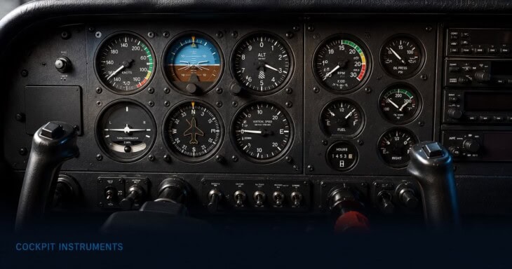
This arrangement is not arbitrary. The attitude indicator is at the centre because it is the reference point for everything else. When a pilot wants to check airspeed, their eyes move left from the attitude indicator and come back to centre. When they check altitude, they move right and come back. The scan flows outward from the centre and returns, over and over, in a rhythm that becomes automatic.
The attitude indicator
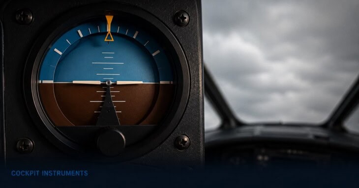
The attitude indicator shows whether the aircraft is level, banking left or right, pitching nose-up or nose-down, or some combination of all of these. It does this by displaying a miniature aircraft symbol against an artificial horizon line, which stays level regardless of what the real aircraft is doing. When the wings on the miniature aircraft are level with the artificial horizon, the real aircraft is flying level. When the miniature aircraft tilts, the real one has banked. This is the most important instrument in the six-pack, and the one that sits at the centre of the T for exactly that reason. In poor visibility, when the pilot cannot see the real horizon outside, the attitude indicator is the instrument that prevents the aircraft from entering an uncontrolled bank or pitch that the pilot might not otherwise feel.
Read the full guide: The Attitude Indicator: The Instrument That Tells Pilots Which Way Is Up
The airspeed indicator
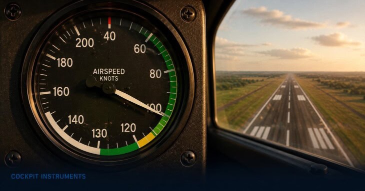
The airspeed indicator shows how fast the aircraft is moving through the air, displayed in knots. The face of the gauge is colour-coded: a white arc marks the range where the flaps can safely be extended, a green arc marks the normal operating speed range, a yellow arc indicates a caution zone where smooth air is required, and a red line marks the speed the aircraft must never exceed. Pilots use these arcs constantly during approach and landing, and the position of the needle against the green arc tells them at a glance whether the aircraft is flying too fast, too slow, or just right for a given phase of flight. Flying too slowly risks a stall; flying too fast risks overstressing the airframe.
Read the full guide: The Airspeed Indicator: How Pilots Know How Fast They’re Flying
The altimeter
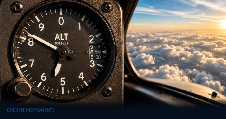
The altimeter shows the aircraft’s altitude, typically in feet above sea level. It works by measuring atmospheric pressure, which decreases predictably as altitude increases. Because pressure also varies with weather, the altimeter has a small dial on its face, called the Kollsman window, where the pilot sets the current local pressure before each flight. Without this adjustment, the altimeter can read hundreds of feet off the actual altitude. Pilots update this setting regularly during a flight, particularly when crossing from one area to another, because the pressure at the surface changes from place to place. Getting the altimeter reading wrong is one of the classic causes of controlled flight into terrain, where an aircraft strikes the ground because the crew believed they were higher than they actually were.
Read the full guide: The Altimeter: How Pilots Read Their Altitude
The heading indicator
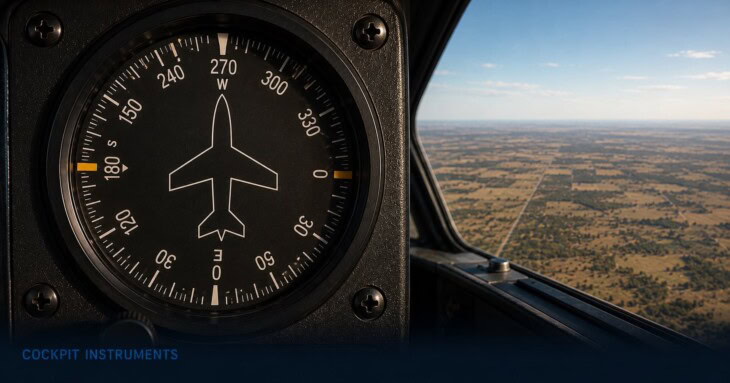
The heading indicator shows the direction the aircraft’s nose is pointing, in degrees, on a rotating compass card. Zero is north, 90 is east, 180 is south, 270 is west. Pilots use it to hold a course, to turn onto a specific heading, and to navigate with precision. You might wonder why a pilot would use a heading indicator when an aircraft already has a magnetic compass. The answer is that a magnetic compass behaves unreliably during turns and acceleration, swinging and lagging in ways that make it very difficult to read accurately in flight. The heading indicator uses a gyroscope and stays steady. The tradeoff is that the gyroscope drifts slightly over time, so pilots must realign the heading indicator with the magnetic compass roughly every fifteen minutes to keep it accurate.
Read the full guide: The Heading Indicator: How Pilots Stay on Course
The vertical speed indicator
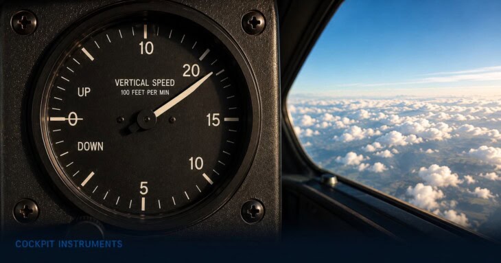
The vertical speed indicator, often called the VSI, shows how quickly the aircraft is climbing or descending, measured in feet per minute. A needle pointing upward means the aircraft is climbing; pointing downward means it is descending; sitting at zero means level flight. Pilots use it to set and maintain a specific rate of climb after takeoff, to control their descent on approach, and to confirm that a manoeuvre is going as intended. One important characteristic of the VSI is that it lags a few seconds behind the aircraft’s actual vertical movement, meaning that if a pilot pushes the nose down, the VSI needle will not respond instantly. Experienced pilots account for this delay and do not chase the needle.
Read the full guide: The Vertical Speed Indicator: How Pilots Control Their Climb and Descent
The turn coordinator
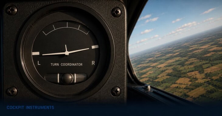
The turn coordinator is the most visually unusual of the six instruments. It contains two separate elements on one face. The upper part shows a small aircraft symbol that banks left or right to indicate the rate of turn: when the wings of the miniature aircraft align with a marked reference line, the pilot is turning at what is called a standard rate, which is three degrees per second and completes a full circle in exactly two minutes. The lower part is a small ball in a curved glass tube filled with liquid. This ball shows whether the turn is coordinated, meaning whether the aircraft is flying cleanly through the air or skidding and slipping. Pilots learn early that the ball should always be centred during a turn, and the technique for keeping it there is the foundation of smooth, efficient flying.
Read the full guide: The Turn Coordinator: How Pilots Keep Their Turns Smooth
How pilots use the six-pack together
No pilot stares at a single instrument. The six-pack only makes sense as a group, read in a pattern. The technique pilots learn is called the instrument scan: a continuous, disciplined movement of the eyes across the panel that builds and maintains a complete picture of the aircraft’s state. In instrument flying conditions, where the pilot cannot see outside the cockpit at all, this scan is the only way to keep the aircraft under control.
The scan is centred on the attitude indicator. A pilot checks it, then moves to one of the other five instruments to gather a specific piece of information, then returns to the attitude indicator before moving to the next. The attitude indicator acts as the reference from which everything else is interpreted. Is the speed where it should be? Check the airspeed indicator, then back to attitude. Is the altitude holding? Check the altimeter, then back to attitude. Is the heading drifting? Check the heading indicator, then back to attitude. Done correctly, this scan becomes a rhythm, and the pilot builds a continuously updated mental model of the flight without fixating on any single instrument for more than a second or two.
This is why the layout matters. Placing the attitude indicator at the centre of the T and the other primary instruments immediately around it keeps the scan tight and fast. Everything a pilot needs is within a small arc of movement from the reference point. It is an elegant design solution, arrived at through decades of experience, and it explains why the arrangement has survived essentially unchanged from 1937 to the present day and why even modern glass cockpit displays preserve the same spatial logic on their screens.
To explore any of the six instruments in depth, follow the links in the sections above. For the full picture of how these instruments fit into a modern cockpit alongside engine gauges and glass displays, see the Airplane Cockpit Instruments Explained overview.
FAQ
Get the Newsletter
The latest aviation news and stories sent to your inbox.
About the Author

Tim is the owner and lead editor of AeroCorner since 2019, overseeing aviation content covering aircraft, airlines, airports, and the broader aviation industry. Through years of researching, writing, editing, and publishing aviation-focused content, he has developed extensive practical knowledge of commercial aviation and air travel. Based in Asia and a frequent traveler himself, Tim also brings firsthand passenger experience to AeroCorner’s coverage. Outside of publishing, he has also explored aviation firsthand through hands-on flight training in New Zealand.