

The descent has to be timed precisely. Too steep and the aircraft arrives over the runway too fast, the approach angle too aggressive to land safely. Too shallow and the pilot floats above the correct glidepath, consuming runway they cannot afford to waste. Somewhere between those two outcomes is the correct rate of descent, and the vertical speed indicator is the instrument that tells the pilot, in feet per minute, exactly how fast the aircraft is moving up or down.
The vertical speed indicator is one of the simpler instruments in the six-pack to read: a single needle, a scale marked in hundreds of feet per minute, and a zero line in the middle. But it has a characteristic that catches out student pilots and occasionally experienced ones too. The instrument lags. When the pilot changes the aircraft’s attitude, the needle does not respond immediately. It catches up over the next several seconds, and a pilot who does not know this will keep correcting, keep chasing the needle, and end up oscillating through the very rate they were trying to hold.
This article explains what the vertical speed indicator shows, how a pilot uses it to manage climbs and descents throughout a flight, and why understanding its lag is as important as reading its numbers.
What the vertical speed indicator shows
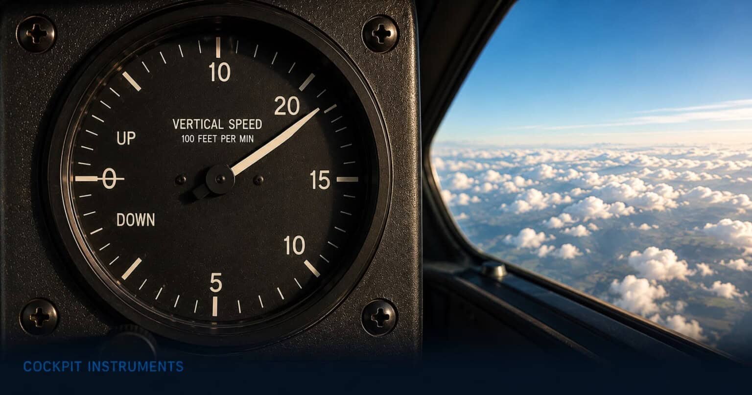
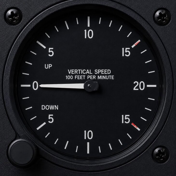
The face of the vertical speed indicator is a simple circular dial with a scale that runs from zero at the centre through climbing and descending ranges. The upper half of the scale covers climbs, measured in feet per minute, typically up to 2,000 fpm. The lower half mirrors this for descents. A single needle sweeps upward from zero to show a climb and downward to show a descent. When the aircraft is flying level with no change in altitude, the needle sits straight across at the zero mark.
The scale markings are in increments of 500 feet per minute. Numbers around the face — 5, 10, 15, 20 — represent 500, 1,000, 1,500, and 2,000 feet per minute, so the scale reads in hundreds. A needle pointing at 5 means the aircraft is climbing or descending at 500 feet per minute. A needle near the top of the scale at 20 means 2,000 feet per minute, which for a light training aircraft is close to its maximum climb capability.
Unlike the airspeed indicator or altimeter, the VSI has no colour arcs and no critical speed markings to memorise. The reading is self-explanatory: up is a climb, down is a descent, and the number tells the pilot how fast. This simplicity is part of what makes it a useful quick reference and part of what makes its lag so easy to mishandle.
The VSI is a trend indicator, not a control instrument
Pilots use the VSI to confirm that an attitude change has produced the expected result, not to drive each correction. The correct technique is to set a pitch attitude and power on the attitude indicator, hold it steady, then check the VSI a few seconds later to verify the result. Correcting each VSI movement as it happens — chasing the needle — fights the instrument’s inherent lag and creates the overcorrections it was supposed to prevent.
How pilots read the vertical speed indicator in flight
In the climb after takeoff, a light training aircraft such as a Cessna 172 will show a vertical speed of around 600 to 700 feet per minute when flown at its best rate of climb speed. The pilot establishes the climb attitude on the attitude indicator, lets the airspeed settle, then glances at the VSI to confirm the expected rate is being achieved. If the VSI shows significantly less than expected, something is off: the aircraft is heavier than usual, a headwind is stronger than forecast, the pitch attitude is too shallow, or the engine is not producing full power. The VSI gives an immediate number that tells the pilot whether the climb is performing as it should.
In cruise at a constant altitude, the VSI needle should sit at zero. If it drifts during what appears to be level flight, the aircraft is gradually climbing or descending — something that can happen after a power change, as the aircraft burns fuel and becomes lighter, or as air temperature or density altitude changes affect performance. The pilot trims the aircraft back to level and verifies on the VSI that the correction held. A tiny positive reading that creeps up over several minutes means the aircraft is very slowly climbing; a pilot who does not catch this during the instrument scan will arrive at altitude check-in slightly above their assigned level.
On descent, the VSI becomes a primary reference alongside the altimeter. A typical approach descent in a light aircraft runs at around 500 feet per minute — shallow enough to give the pilot time to manage the approach, steep enough to reach the threshold at the correct height. On a standard 3-degree instrument approach glideslope at 90 knots of groundspeed, the required descent rate is approximately 480 feet per minute. At 100 knots, closer to 530. Pilots learn these rule-of-thumb numbers for the approaches they fly regularly so they can set up the correct rate without having to calculate it each time. The VSI then confirms they are on the right track.
During the approach itself, the pilot uses the VSI as a cross-check rather than the primary reference. The primary references on an instrument approach are the glideslope indicator and the altimeter. The VSI confirms the rate of descent is consistent with a stable approach: a steady 500 fpm reading alongside a correctly tracking glideslope and a reducing altimeter is the picture of a controlled, stable approach. A VSI swinging between 300 and 800 fpm suggests the pilot is hunting, the approach is not stabilised, and a go-around is likely the correct decision.
What pilots watch out for
The VSI works by comparing the current static pressure from the pitot-static system to the pressure inside the instrument’s sealed case, which changes more slowly through a calibrated restrictor. The rate at which the pressure differential builds determines what the needle shows. Because of this restriction, there is an unavoidable delay between the moment the aircraft changes its vertical speed and the moment the needle catches up. The FAA cites this lag as typically six to nine seconds. That is long enough for a lot of unnecessary corrective input to be made.
The classic failure from this lag is called chasing the needle. A pilot on approach pushes the nose down slightly to increase the descent rate. The VSI does not immediately respond. Thinking the correction was insufficient, the pilot pushes further. Six seconds later the VSI registers both corrections combined and swings well past the target. The pilot pulls back. The needle swings the other way. The result is a slow pitch oscillation — the aircraft seesawing while the pilot reacts to each past input as if it were the current one. The pattern is common enough in training that instructors specifically teach students to make one attitude adjustment, hold it steadily, and wait for the VSI to settle before making another.
The VSI is also unreliable in turbulence. In rough air, the needle swings erratically as the aircraft bumps through pressure variations that have nothing to do with its actual climb or descent rate. Trying to hold a precise rate of descent in turbulence by chasing the VSI will produce constant, futile inputs. The correct technique is to set an appropriate pitch attitude and power combination and accept that the VSI will give only a general indication of the trend until the air smooths out.
A blocked static port stops the VSI from working entirely. With the static system sealed — by ice, water, or an insect in the port — no pressure changes reach the instrument, and the needle freezes at zero regardless of what the aircraft is doing. A VSI sitting motionless at zero while the aircraft is visibly climbing or descending is a clear symptom of a static system blockage and should prompt immediate cross-checking of the altimeter and airspeed indicator. Both will also behave abnormally: the altimeter will stop moving, and the airspeed indicator will begin to drift inaccurately. Recognising these failures together, rather than misreading each instrument in isolation, is part of what instrument training teaches.
The vertical speed indicator in a glass cockpit
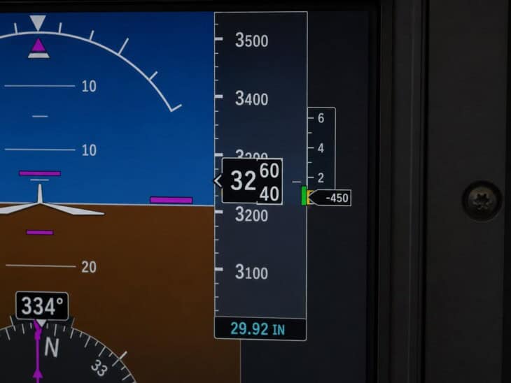
On a glass cockpit Primary Flight Display, vertical speed is shown as a small vertical scale or digital readout positioned alongside the altitude tape, usually on the right side of the screen. A number displays the current vertical speed in feet per minute. The electronic sensing used in glass cockpit systems has considerably less lag than a mechanical VSI: rather than waiting for pressure to equalise through a physical orifice, the solid-state sensors can detect rate of pressure change almost immediately. This makes the electronic readout a more responsive reference and reduces the temptation to over-correct.
Some glass cockpit systems also display a required vertical speed during instrument approaches — a target rate of descent calculated from the published glideslope angle and the aircraft’s current groundspeed, shown alongside the actual reading so the pilot can compare the two at a glance. A green or white bug on the VSI tape marks the target; the pilot simply aims to keep the actual reading aligned with it. This removes much of the mental arithmetic from approach flying, particularly when the groundspeed changes due to wind, and gives the pilot a direct comparison between where the descent rate is and where it needs to be.
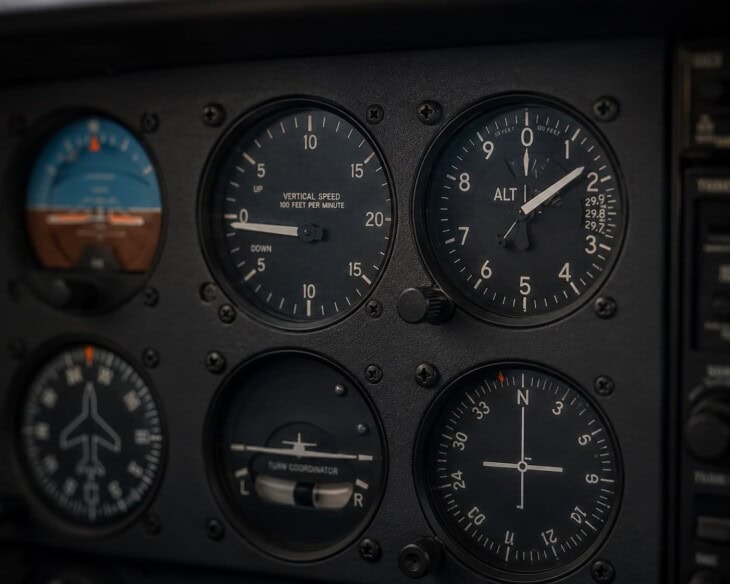
The vertical speed indicator is part of the six instruments that make up the six-pack, sitting at the bottom right of the basic T. It works in close partnership with the altimeter directly above it — the altimeter shows where the aircraft is, the VSI shows how fast it is getting there. The attitude indicator at the centre of the T provides the pitch reference from which the VSI reading follows. For the complete overview of how all cockpit instruments fit together, see Airplane Cockpit Instruments Explained.
FAQ
Get the Newsletter
The latest aviation news and stories sent to your inbox.
About the Author
Tim is the owner and lead editor of AeroCorner since 2019, overseeing aviation content covering aircraft, airlines, airports, and the broader aviation industry. Through years of researching, writing, editing, and publishing aviation-focused content, he has developed extensive practical knowledge of commercial aviation and air travel. Based in Asia and a frequent traveler himself, Tim also brings firsthand passenger experience to AeroCorner’s coverage. Outside of publishing, he has also explored aviation firsthand through hands-on flight training in New Zealand.