

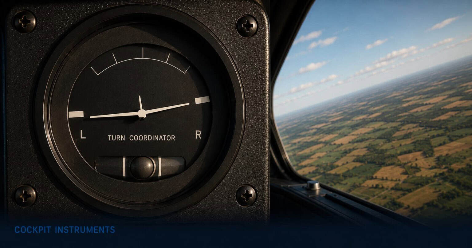
The turn coordinator is the most visually unusual instrument in the six-pack, and the one that most reliably confuses students when they first encounter it. It looks like two instruments sharing a single face: the upper half shows a miniature aircraft that banks left or right to indicate the rate of a turn, and the lower half shows a small ball rolling inside a curved glass tube filled with liquid. The miniature aircraft tells the pilot how fast the aircraft is turning. The ball tells the pilot whether the turn is being done well.
Understanding both elements — and the relationship between them — is one of the earliest things a student pilot learns, and keeping the ball centred is one of the habits that distinguishes smooth, efficient flying from sloppy flying. An aircraft whose ball is persistently off-centre is generating more drag than it needs to, burning more fuel than necessary, and in certain situations, setting up a condition that can become dangerous very quickly.
This article explains what both elements of the turn coordinator show, how pilots use the instrument through the phases of a flight, and why the small ball in its glass tube is more safety-critical than it appears.
What the turn coordinator shows
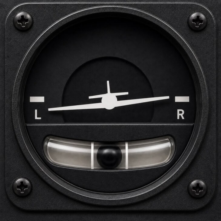
The face of the turn coordinator is split into two distinct sections. The upper section contains a miniature aircraft symbol — a small silhouette viewed from slightly behind and above, with swept wings — set against a white or grey background. On either side of the instrument centre are two reference marks labelled L and R. When the aircraft is turning right, the miniature aircraft tilts to the right. In a left turn, it tilts left. In straight and level flight, it sits level.
The reference marks are what make the display useful. When the tip of the miniature aircraft’s wing aligns with the L or R reference mark, the aircraft is turning at standard rate: exactly three degrees per second. At standard rate, a full 360-degree turn takes two minutes. A 180-degree turn — a course reversal — takes one minute. A 90-degree turn takes thirty seconds. ATC uses standard rate turns as the baseline in instrument procedures, and the turn coordinator makes achieving that rate simple: bank until the wing tip touches the mark, then hold it there.
One point that catches many new pilots out: the miniature aircraft in the turn coordinator does not show bank angle. It shows rate of turn. A fast aircraft needs more bank to produce a standard rate turn than a slow aircraft, so the wing position on the turn coordinator will look the same at standard rate regardless of speed — but the actual bank angle being flown is different. This is the opposite of the attitude indicator, where the miniature aircraft position directly reflects the real bank angle. Mixing the two instruments up in the scan is a common early error.
The lower section is the ball: a small sphere sitting inside a curved glass tube filled with liquid. The ball rolls freely from side to side within the tube. When the aircraft is in coordinated flight — with rudder and ailerons working together so the aircraft is flying cleanly through the air — the ball sits at the marked centre of the tube. When the flight is uncoordinated, the ball rolls toward whichever side the aircraft is slipping or skidding.
What the ball is telling you
Ball centred: coordinated flight — rudder and ailerons balanced. Ball to the inside of the turn: slip — insufficient rudder for the bank angle applied. Ball to the outside of the turn: skid — too much rudder for the bank angle applied. Correction in all cases: press the rudder pedal on the same side as the ball. Pilots call this “step on the ball.”
How pilots read the turn coordinator in flight
Every time a pilot enters a turn, two things must happen together: the wings must bank to the correct angle to produce the desired rate of turn, and the rudder must be applied in step with the ailerons to keep the aircraft coordinated. The turn coordinator provides instant feedback on both. To enter a standard rate turn, the pilot banks until the miniature aircraft’s wing tip touches the reference mark, then simultaneously applies enough rudder to keep the ball centred. Done correctly, the result is a smooth, coordinated turn at three degrees per second.
Keeping the ball centred requires active rudder input throughout the turn. Many student pilots focus entirely on the bank angle and forget the ball, resulting in a constant slight skid as the aircraft turns faster than the rudder is keeping up with. Experienced pilots develop a habit of glancing at the ball as naturally as checking the airspeed, making small corrections with the feet without consciously thinking about it. The mnemonic is simple: if the ball is on the right, press the right rudder pedal. If it is on the left, press the left rudder pedal. Step on the ball.
The turn coordinator also enables timed turns, which become important when flying without a working heading indicator. At standard rate, every 30 seconds of turning produces exactly 90 degrees of heading change. A pilot who needs to turn from 090° to 360° — a 90-degree left turn — times 30 seconds from the moment the wings hit the standard rate reference mark and then rolls out. This technique requires a clock and the turn coordinator, and nothing else. It is the foundation of partial panel flying: after a vacuum pump failure takes out the heading indicator and attitude indicator, the turn coordinator — which is electrically powered and continues working independently — becomes the only instrument the pilot has to control their direction in cloud.
In straight and level cruise, the turn coordinator is less frequently referenced than the other instruments, but the ball still matters. Even in straight flight, an aircraft with a heavy fuel imbalance or asymmetric loading will require constant rudder input to keep the ball centred, and a pilot who is not correcting will be burning more drag and fuel than necessary. Checking the ball occasionally in cruise and making a small trim or rudder correction if needed is part of maintaining an efficient flight.
What pilots watch out for
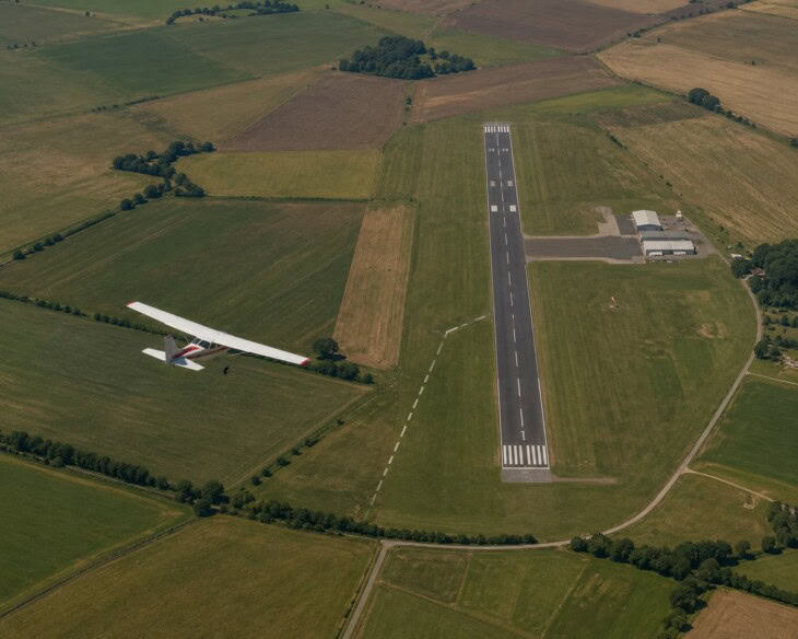
The turn coordinator’s most dangerous context is not in cruise flight at altitude. It is in the traffic pattern, close to the ground, during the turn from base leg onto final approach. This manoeuvre has been identified by the AOPA Air Safety Institute as one of the most common scenarios in fatal general aviation accidents, and the turn coordinator — specifically the ball — is the instrument that warns a pilot when they are about to set it up.
The scenario unfolds like this: the pilot turns from base leg onto final and overshoots the extended runway centreline. The instinct is to push on the inside rudder to swing the nose back toward the runway — but without adding additional bank to match. This produces a skid: the aircraft is yawing faster than it is banking, the ball rolls to the outside of the turn, and the inside wing is now at a higher angle of attack than the outside wing. If the aircraft is also flying slowly — as it should be on approach, near its stall speed — the inside wing stalls while the outside wing continues to fly. The aircraft rolls sharply toward the stalled wing, often entering an incipient spin. At three hundred feet above the ground, there is no altitude to recover. The correct fix, at the first sign of an overshoot, is to roll into more bank rather than apply more rudder — but this requires a pilot who knows what the ball is telling them and acts on it.
The base-to-final turn: one of general aviation’s most persistent killers
The AOPA Air Safety Institute has documented the low-altitude stall/spin as one of the leading causes of fatal accidents in light aircraft, with a significant proportion occurring specifically in the base-to-final turn. The typical mechanism is a cross-control input — inside rudder without matching bank — that skids the aircraft and loads the inside wing beyond its stall angle at exactly the worst altitude to recover. Stall/spin accidents in the traffic pattern are almost always fatal because there is no height for recovery. The ball in the turn coordinator is the instrument that shows the pilot a skid is developing — but only if they are watching it.
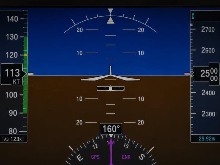
The other common misunderstanding is treating the turn coordinator as an attitude instrument. The miniature aircraft symbol is visually similar enough to the attitude indicator’s miniature aircraft that students sometimes scan the two instruments interchangeably. But the information they display is fundamentally different: the attitude indicator shows the actual bank angle of the real aircraft, while the turn coordinator shows the rate of turn. A fast aircraft can produce a standard rate turn at 20 degrees of bank; a slow aircraft may need 15 degrees for the same rate. The miniature aircraft in the turn coordinator will show the same position for both, even though the actual bank angles are different. Recognising this distinction — and reading each instrument for what it actually shows — is a key milestone in instrument flying training.
The turn coordinator in a glass cockpit
In glass cockpit aircraft, the turn coordinator as a standalone gauge disappears, but the information it provides is carried over into the Primary Flight Display in a different form. Turn rate is visible through the movement of the heading tape at the bottom of the display — a pilot can observe how quickly the heading number is changing and adjust to achieve the standard rate. Some systems also show a trend vector or rate-of-turn arc on the compass rose. The slip/skid information — the ball — appears as a small horizontal displacement bar beneath the miniature aircraft on the attitude display, sliding left or right to indicate uncoordinated flight. Keeping this bar centred requires exactly the same rudder technique: step on the bar.
The turn coordinator’s role as the critical electric backup instrument also diminishes in glass cockpit aircraft. Because the AHRS that drives the glass cockpit’s attitude and heading displays uses solid-state electronics rather than a vacuum pump, vacuum failure does not take out the primary instruments. The situation that made the electric turn coordinator so important in analogue aircraft — the dual loss of attitude indicator and heading indicator after a pump failure — simply does not arise in the same way. The glass cockpit retains a slip/skid indicator, but its status as the sole remaining navigation tool after a failure is no longer relevant.
The turn coordinator completes the six instruments of the six-pack, sitting at the bottom left of the panel alongside the vertical speed indicator. It is the only instrument in the six-pack driven by an electric gyro rather than the vacuum system, which is precisely why it survives a vacuum failure when the attitude indicator and heading indicator do not. For the full picture of how all six instruments work together and how they translate into a modern glass cockpit, see Airplane Cockpit Instruments Explained.
FAQ
Get the Newsletter
The latest aviation news and stories sent to your inbox.
About the Author
Tim is the owner and lead editor of AeroCorner since 2019, overseeing aviation content covering aircraft, airlines, airports, and the broader aviation industry. Through years of researching, writing, editing, and publishing aviation-focused content, he has developed extensive practical knowledge of commercial aviation and air travel. Based in Asia and a frequent traveler himself, Tim also brings firsthand passenger experience to AeroCorner’s coverage. Outside of publishing, he has also explored aviation firsthand through hands-on flight training in New Zealand.