

Table of Contents
Every aircraft has two speeds the pilot must never cross. One is the stall speed: fly too slowly and the wings stop generating lift, the aircraft stops flying, and the nose pitches down abruptly. The other is the never-exceed speed: fly too fast and the forces acting on the airframe exceed what it was built to handle, with potentially catastrophic consequences. Between those two limits is the safe flying envelope, and the airspeed indicator is the instrument that tells the pilot exactly where they are within it at every moment of a flight.
The airspeed indicator sits at the top left of the six-pack, to the left of the attitude indicator in the basic T arrangement. Its face is colour-coded with arcs and a red line that communicate speed limits without the pilot needing to remember a set of numbers. A single glance at where the needle sits relative to those colours tells the pilot whether the aircraft is flying safely, flying dangerously slowly, or approaching its structural limits. It is one of the most immediately readable instruments in the cockpit.
This article explains what the airspeed indicator shows, how the colour system works, how pilots use it across a flight, and why a small tube on the outside of the aircraft is the single point of failure that can render the whole instrument useless.
What the airspeed indicator shows
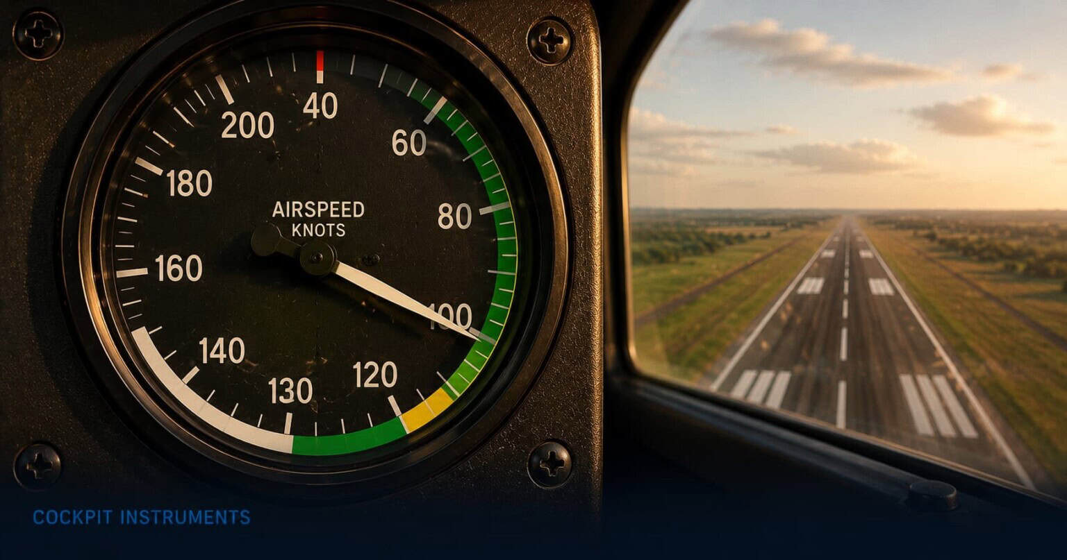
The airspeed indicator shows how fast the aircraft is moving through the air, displayed in knots. This is called indicated airspeed, and it is the value pilots use for almost all flying decisions because the aircraft’s aerodynamic behaviour, including the speed at which it stalls, is governed by the pressure of the air flowing over the wings rather than actual speed over the ground. The needle sweeps around the dial from zero, and the face of the instrument is divided into coloured arcs and a single red line, each marking a specific speed limit or range.
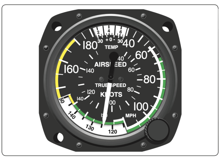
The white arc covers the lowest speed range on the dial. Its bottom end marks Vso, the stall speed in the landing configuration with flaps fully extended. Its top end marks Vfe, the maximum speed at which the flaps can safely be used. Any time the flaps are extended, the pilot should be flying within the white arc. Descending below the bottom of the white arc with flaps down means the aircraft is approaching a stall.
The green arc covers the normal operating range. Its bottom end marks Vs1, the stall speed in the clean configuration with flaps and gear retracted. Its top end marks Vno, the maximum structural cruising speed. This is where the aircraft is designed to operate in normal flight. A pilot in cruise with the needle anywhere in the green arc is flying in the correct speed range for that aircraft.
Above the green arc is the yellow arc, which extends from Vno up to Vne, the never-exceed speed. The yellow arc is a caution zone: the aircraft can fly at these speeds, but only in smooth air. In turbulence, the additional loads imposed on the structure at yellow-arc speeds could cause damage. Pilots encountering unexpected turbulence while flying in the yellow arc slow down immediately.
A single red line at the top of the yellow arc marks Vne, the never-exceed speed. Above this, structural failure becomes a real possibility. The red line is not a suggestion. Most aircraft also have a manoeuvring speed, known as Va, which is the maximum speed at which the pilot can apply full control deflection without risking structural damage. Va is not marked on the airspeed indicator face but is published in the aircraft’s flight manual and memorised by the pilot.
The airspeed arcs at a glance
White arc: flap operating range (bottom = stall with flaps, top = max flap speed). Green arc: normal operating range (bottom = stall clean, top = max structural cruise speed). Yellow arc: caution, smooth air only. Red line: never exceed.
How pilots read the airspeed indicator in flight
During the takeoff roll, the airspeed indicator is the first instrument to come alive. As the aircraft accelerates down the runway and air begins flowing into the pitot tube, the needle rises from zero. The pilot watches it climb toward the rotation speed, the speed at which they pull back on the controls and the nose lifts. In a typical light training aircraft such as a Cessna 172, this is around 55 knots. The pilot does not guess: they watch the airspeed indicator and rotate at the published speed.
After takeoff, the pilot climbs at a target airspeed that gives the best rate of climb for the aircraft. They refer to the airspeed indicator to hold that speed precisely, adjusting the pitch of the nose up or down to keep the needle on the target. Too much nose-up and the aircraft climbs steeply but slowly, and the airspeed bleeds off toward the stall. Too much nose-down and the aircraft climbs quickly in terms of airspeed but shallowly in terms of actual altitude gain. Finding the right pitch for the right airspeed is one of the first skills a student pilot develops.
In cruise, the needle should sit comfortably in the green arc. The pilot trims the aircraft so it holds that speed without constant input, then scans the airspeed indicator as part of the regular instrument scan to confirm nothing is drifting. On a long flight, changes in altitude, temperature, or power setting can cause airspeed to creep up or down, and the pilot makes small adjustments to keep it in range.
On the approach to landing, the white arc becomes the relevant reference. As the pilot extends the flaps in stages, the aircraft slows and the approach speed drops toward the white arc. A typical approach in a light aircraft is flown at around 65 to 75 knots, well within the white arc and safely above the stall speed. Flying too slowly on approach is one of the leading causes of stall-spin accidents, where the aircraft stalls close to the ground and there is not enough altitude to recover. The airspeed indicator is the pilot’s continuous warning system against this.
What pilots watch out for
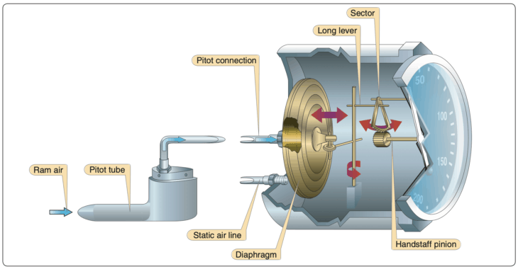
The airspeed indicator depends entirely on a small forward-facing probe on the outside of the aircraft called the pitot tube. This tube points into the airflow and measures the pressure of the air hitting it. The instrument compares this dynamic pressure to the static pressure from a separate port elsewhere on the aircraft, and the difference between the two gives the airspeed reading. If the pitot tube becomes blocked, the airspeed indicator stops working. The needle may freeze, climb misleadingly, or drop to zero depending on how and where the blockage occurs.
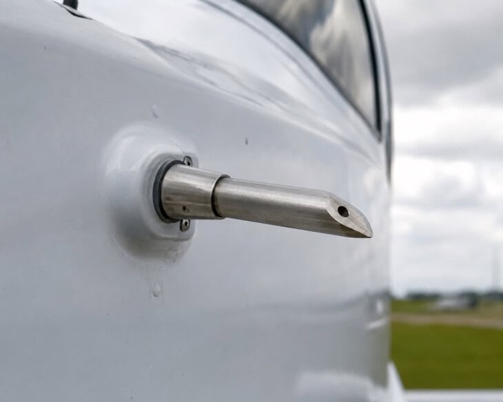
The most common cause of pitot tube blockage is ice. As an aircraft climbs through cloud, supercooled water droplets can freeze inside the tube, blocking it within seconds. All aircraft certificated for flight in icing conditions have an electrically heated pitot tube, and pilots are trained to switch on pitot heat before entering cloud or visible moisture. Forgetting to do so is a recurring error in accident reports. The pitot tube can also be blocked by insects nesting in it while the aircraft is parked, something that is supposed to be caught during the preflight inspection but has caused accidents when it was not.
When the pitot tube fails: two accidents
In 1996, Birgenair Flight 301 crashed into the Atlantic shortly after takeoff from the Dominican Republic. The captain’s pitot tube had been blocked by a wasp nest during the time the aircraft was parked outdoors. The resulting false airspeed readings caused confusion and ultimately loss of control. All 189 people on board were killed. In 2009, Air France Flight 447 entered a high-altitude stall over the Atlantic after its pitot probes became blocked by ice crystals, causing unreliable airspeed readings and disconnecting the autopilot. The crew were unable to recover, and 228 people died. Both accidents are now core case studies in the dangers of pitot system failure and the importance of unreliable airspeed training.
When a pilot encounters an unreliable airspeed reading in flight, the response is a specific procedure trained for exactly this situation. Power and pitch are set to known values for the phase of flight, and the pilot navigates by attitude and engine power rather than by airspeed until the situation can be resolved or a landing made. Modern commercial airline training devotes significant time to this scenario precisely because the accidents mentioned above demonstrated that even experienced crews can be caught off guard when the instrument they rely on most suddenly gives contradictory or frozen readings.
The airspeed indicator in a glass cockpit
On a glass cockpit Primary Flight Display, airspeed is shown as a vertical tape on the left side of the screen.
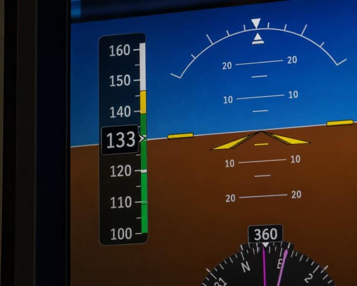
A large number in the centre of the tape shows the current indicated airspeed, and the tape scrolls up and down as speed changes. The colour arcs from the analogue dial are preserved: the tape is shaded with the same white, green, and yellow zones, and the red line appears at the top.
Bug markers, small moveable indicators on the tape, allow the pilot to set target speeds for approach or climb so that a target speed is always visible as a reference point on the tape. The information is the same as on the analogue dial; it is simply presented in a format that integrates more naturally with the other flight data around it on the screen.
The airspeed indicator is part of the six instruments that make up the six-pack. Its two neighbours in the basic T are the attitude indicator at the centre and the altimeter to the right. For the complete picture of how all cockpit instruments fit together, including engine gauges and glass displays, see Airplane Cockpit Instruments Explained.
FAQ
Get the Newsletter
The latest aviation news and stories sent to your inbox.
About the Author
Tim is the owner and lead editor of AeroCorner since 2019, overseeing aviation content covering aircraft, airlines, airports, and the broader aviation industry. Through years of researching, writing, editing, and publishing aviation-focused content, he has developed extensive practical knowledge of commercial aviation and air travel. Based in Asia and a frequent traveler himself, Tim also brings firsthand passenger experience to AeroCorner’s coverage. Outside of publishing, he has also explored aviation firsthand through hands-on flight training in New Zealand.