


Table of Contents
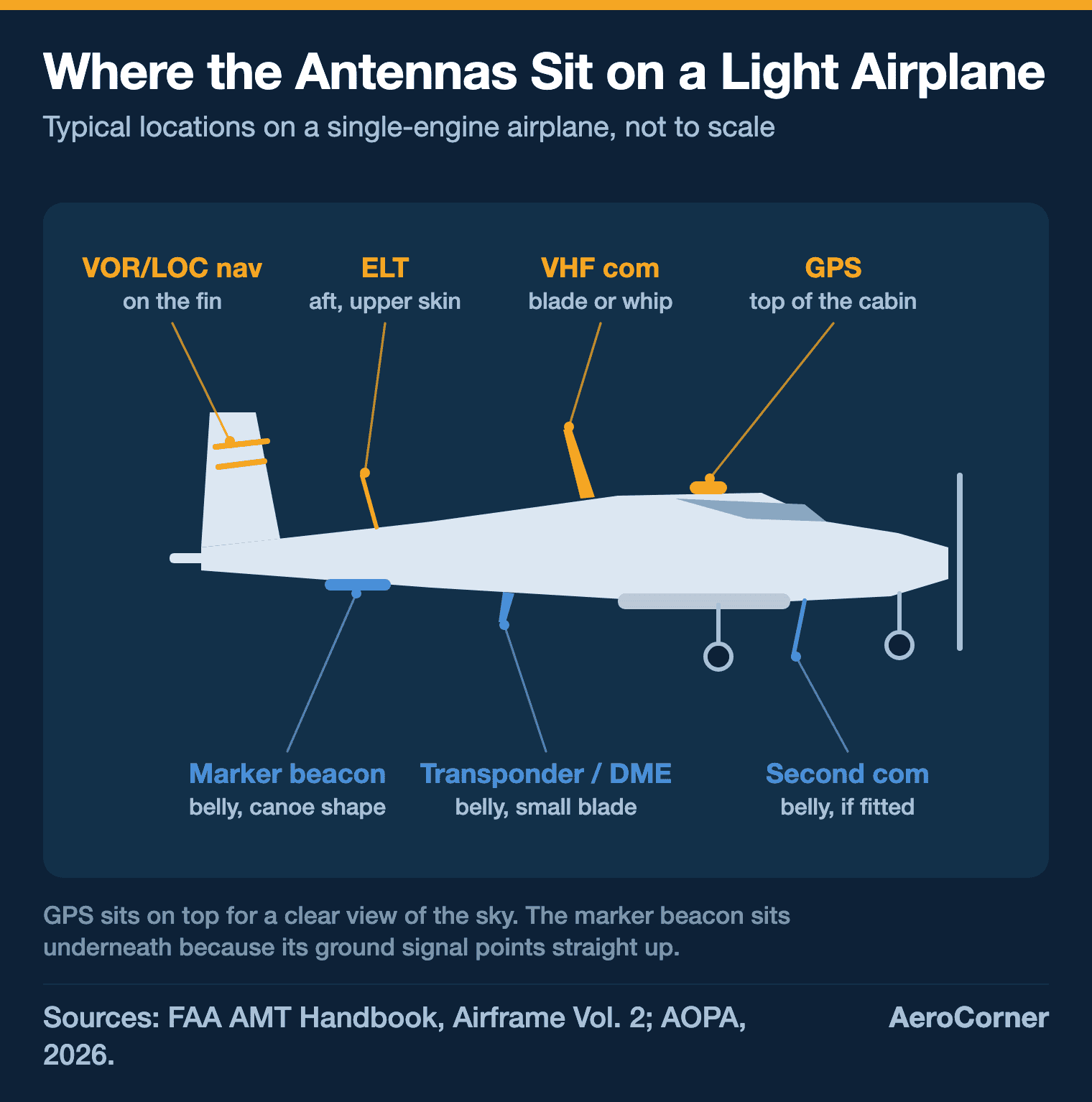
Every blade, whip, puck and dome on an airplane’s skin is an antenna, and most serve a single radio system, though a few are shared. A light single carries a handful: VHF com, a VOR/localizer nav antenna, GPS, a transponder blade, a marker beacon and an ELT. An airliner adds radio altimeters, TCAS, weather radar and satellite communications, and long-range jets add HF.
Where each antenna sits is set by its frequency and by where its signal comes from. GPS and satellite antennas face the sky, so they ride on top. Antennas that listen to a station or the ground directly below, like the marker beacon and the radio altimeter, sit on the belly.
The table below covers the 14 types you will find on airplanes flying today, with the frequency each one uses. It leaves out Loran, which older guides often still list: the US switched it off in 2010.
| Antenna | What it does | Frequency | Usual location |
|---|---|---|---|
| VHF com | Voice with ATC and other aircraft | 118.0 to 136.975 MHz | Top or belly |
| HF | Long-range voice over oceans | 2 to 25 MHz | Tail fin, on long-range aircraft |
| VOR/localizer | Course guidance en route and on approach | 108 to 117.95 MHz | Vertical tail |
| Glideslope | Vertical guidance on an ILS | 329.3 to 335.0 MHz | Nose, or shared with the VOR antenna |
| Marker beacon | Position along an ILS approach | 75 MHz | Belly |
| Transponder and DME | Radar replies and distance to a station | 1030/1090 MHz; 962 to 1213 MHz | Belly |
| TCAS | Traffic alerts and avoidance | 1030/1090 MHz | Top and belly on airliners |
| ADS-B | Broadcasts GPS position | 1090 MHz or 978 MHz | Transponder antenna or its own |
| GPS | Satellite position | 1575.42 MHz | Top of the fuselage |
| ELT | Crash locator | 406 MHz, plus 121.5 MHz | Aft upper fuselage or tail |
| Radio altimeter | Height above the ground | 4.2 to 4.4 GHz | Belly, in pairs |
| Weather radar | Precipitation ahead | SHF, such as 9.375 GHz | Inside the nose radome |
| ADF and lightning detector | Bearing to a station or a strike | Low and medium frequency | Low-profile housing |
| Satcom and Wi-Fi | Passenger internet, TV and data links | Ku- and Ka-band | Radome on top |
How to Identify an Aircraft Antenna: Three Basic Designs
The FAA’s Aviation Maintenance Technician Handbook names three basic antenna types used in aviation: the dipole, the Marconi and the loop. Once you know the three, many of the shapes on a ramp start to make sense.
A dipole is a conductor about half the wavelength of its frequency, fed in the middle. The V-shaped VOR antenna on many tails is the classic example: each arm is a quarter wavelength, and together they make a half-wave antenna.
A Marconi antenna is only a quarter wavelength long. It gets away with that because the metal skin of the airplane acts as the missing quarter, called the ground plane. Most VHF com antennas are Marconi antennas, which is why they stand up from the skin.
A loop antenna bends the conductor into a loop, which makes it compact, sturdy and highly sensitive to direction. That direction sense is exactly what an ADF or a lightning detector needs.
Why a com antenna is about two feet tall
Antenna size follows wavelength. The FAA handbook puts a half wavelength across the VHF com band at 3.44 to 3.96 feet (1.05 to 1.21 m), so a quarter-wave Marconi antenna works out to roughly 21 to 24 inches (52 to 60 cm). A GPS signal at 1575.42 MHz has a wavelength more than 10 times shorter, and GPS antennas are small pucks.
On a fabric or composite airplane there is no metal skin to finish the antenna. Installers fit foil, conductive plates or wires under the skin to create the ground plane, and some composite airplanes have antennas built into the structure itself.
Communication Antennas
1. VHF Com Antennas
VHF com antennas carry almost every radio call between pilots and air traffic control. The band runs from 118.0 to 136.975 MHz, split into 720 channels 25 kHz apart, while Europe divides it further into 8.33 kHz channels.
Each com radio has its own antenna, mostly for redundancy, and it can sit on the top or the bottom of the fuselage. The vertical stabilizer or a gear door can shadow an antenna and shorten its range.
When a controller says your signal is five by five, the antenna is doing its job.
Com antennas are vertically polarized, and many aircraft antennas are mounted at a slight angle. The tilt lets them catch a weak signal, rather than none, when the station’s antenna is not lined up with theirs.

2. HF Antennas
VHF only works in line of sight, which is useless halfway across an ocean. HF radio, between 2 and 25 MHz, bounces off the ionosphere and reaches far beyond the horizon, so transoceanic aircraft carry it for long-range voice.
Boeing’s antenna map of the 787 below places its HF antennas in the tail.

3. Satcom and Wi-Fi Antennas
The large hump on top of many airliners is a radome, a weatherproof cover over a satellite antenna. Boeing described one of its own as roughly the size of a car-top luggage carrier, built for Ku- and Ka-band satellite links.
On an airliner with satellite internet, the passenger connection runs through that dome. The full story of how airplanes get Wi-Fi also covers the air-to-ground systems that skip satellites.

Navigation Antennas
4. VOR and Localizer Antennas
The VOR ground stations that define the Victor airways broadcast between 108 and 117.95 MHz. The aircraft receives them on a horizontally polarized antenna, most often a V-shaped dipole, which the FAA handbook notes is least sensitive to signals arriving head-on.
Nav antennas are almost always on the vertical tail, in three common styles. Cat whiskers are rods angled out from each side of the fin, dual blades sit one per side, and towel bars look like the bathroom fixture they are named after.
The same antenna usually feeds the localizer, the left-right half of an instrument landing system, which sits in the lower VOR band from 108 to 111.95 MHz. One nav antenna often serves several receivers, so a failed nav antenna can take out more than one system at once.
5. Glideslope Antennas
The glideslope gives vertical guidance down a slope of about 3 degrees to the runway, on UHF frequencies between 329.3 and 335.0 MHz. The receiver tunes itself automatically when the pilot dials in the paired localizer frequency.
A common setup is a small dipole mounted inside a non-metallic nose. Antenna makers also build glideslope reception into the same dipole used for VOR and localizer, and blade-type glideslope antennas are used too.
6. Marker Beacon Antennas
Marker beacons tell a pilot how far along an ILS approach they are. Each beacon transmits a narrow 75 MHz signal straight up: the outer marker sits 4 to 7 miles (6 to 11 km) from the threshold and lights a blue lamp, the middle marker about 3,500 feet (1,070 m) out and lights an amber one.
Because the signal points straight up, the aircraft antenna has to be on the belly, almost directly over the station. The most common type looks like a small canoe about 10 inches (25 cm) long, though some Cessnas use a flat plate under the tail or a bent wire instead.
7. GPS Antennas
GPS satellites orbit about 12,600 miles (20,300 km) up, and civil receivers use the L1 signal on 1575.42 MHz. By the time it arrives, that signal is weak and easily blocked by the airframe, so the antenna goes at the very top of the fuselage and carries a built-in amplifier.
Com radios can interfere with GPS, so installers keep the two antennas as far apart as they can, sometimes moving a com antenna to the belly to do it. GPS is also the backbone of modern area navigation (RNAV).

8. ADF and Lightning Detector Antennas
An automatic direction finder points to a ground transmitter on low or medium frequency, including ordinary AM radio stations. Modern units pair a fixed loop antenna with an omnidirectional sense antenna, usually in one low-profile housing, which removes any doubt about whether the station is ahead or behind.
Lightning detectors work the same way, because a lightning strike gives off its own radio signal. A loop antenna finds the bearing to each strike, and some systems simply share the ADF antenna. A dedicated display can plot strikes up to 200 miles (320 km) away.
Surveillance and Safety Antennas
9. Transponder and DME Antennas
Ground radar interrogates an aircraft’s transponder on 1030 MHz, and the transponder replies on 1090 MHz with one of 4,096 codes and, in Mode C or S, its altitude. Codes 7500, 7600 and 7700 are reserved for emergencies.
Distance measuring equipment (DME) works in the same UHF neighborhood, 962 to 1213 MHz, timing a pulse to a ground station and back. Its antenna is usually a small blade under the fuselage centerline.
Both use antennas only about 4 inches (10 cm) long, usually on the belly, and one antenna can serve both because the transponder frequency falls inside the DME band. Spike antennas are tuned to the transponder only, while broadband blades suit DME.
Every 24 months, not twice a year
Under 14 CFR 91.413, a transponder used in controlled airspace must be tested and inspected every 24 calendar months. That is a biennial check. The old version of this page called it biannual, which would mean twice a year.
10. TCAS Antennas
TCAS turns the transponder into an air-to-air radar: it interrogates nearby aircraft on 1030 MHz and reads their 1090 MHz replies. Both the A320 and 787 antenna maps on this page show TCAS antennas on the top and the bottom of the fuselage.
TCAS II issues climb or descend commands, while TCAS I only gives traffic advisories. The FAA’s maintenance handbook lists TCAS II for aircraft with more than 30 seats or over about 33,000 pounds (15,000 kg), and TCAS I for aircraft with 10 to 30 seats.

11. ADS-B Antennas
ADS-B Out broadcasts the aircraft’s GPS position, altitude and velocity to controllers and other traffic. It uses one of two links: 1090 ES, an extension of the Mode S transponder signal, or a 978 MHz universal access transceiver (UAT).
A UAT needs its own omnidirectional antenna in addition to the GPS antenna. Since January 1, 2020, 14 CFR 91.225 has required ADS-B Out in Class A, B and C airspace and other listed areas, and the 978 MHz link only counts below 18,000 feet (5,500 m).
12. ELT Antennas
An emergency locator transmitter fires on its own after a crash. A modern unit sends a digital burst on 406 MHz every 50 seconds at 5 watts for at least 24 hours, which COSPAS-SARSAT satellites can locate to within about 1.2 to 3 miles (2 to 5 km), or about 330 feet (100 m) when the signal carries GPS coordinates.
The ELT is mounted as far aft as practical, just ahead of the tail, and its antenna is usually a flexible whip on the upper skin of the tail, built to survive the landing nobody planned. Modern ELTs may also send an analog 121.5 MHz signal for homing, though satellites stopped relaying 121.5 MHz in 2009.
Radar Antennas
13. Radio Altimeter Antennas
A radio altimeter measures height above the ground directly, unlike the pressure-based altimeter on the panel. It sends a 4.3 GHz signal straight down from one belly antenna and catches the echo with a second, which is why these antennas come in pairs.
It is used mainly below 2,500 feet (760 m) and supplies the height for decision height on a low-visibility landing. Radio altimeters work in the 4.2 to 4.4 GHz band, close to the 3.7 to 3.98 GHz C-band that 5G networks began using in 2022.
The FAA had airlines fit 5G-tolerant altimeters or filters, and the whole US airline fleet was upgraded by the end of September 2023.
14. Weather Radar Antennas
Weather radar usually lives behind a non-metallic nose cone, transmitting in the SHF range, such as 5.44 or 9.375 GHz. On high-performance aircraft the antenna is gimbaled and stabilized so it stays aimed at the weather while the airplane maneuvers.
The radome may only be painted with approved paint, or the radar beam cannot get through. Technicians should not run the radar in a hangar without radio-absorbing material, toward a building or during refueling, and never look into a transmitting antenna.
What Happened to Loran Antennas?
Loran-C was a long-range navigation system that fixed an aircraft’s position from chains of towers all broadcasting on 100 kHz. For years it was a standard entry in any list of aircraft antennas.
Loran has been off since 2010
The US Coast Guard began shutting down Loran-C on February 8, 2010, with all transmissions to end by October 1, 2010, under the 2010 Homeland Security appropriations act, after the Department of Homeland Security said it was not needed as a backup for GPS. Any Loran antenna still on an airplane is dead weight, and the FAA’s maintenance handbook now says Loran is no longer available in the United States.
Why Antenna Placement Matters
Antenna placement is always a compromise between mounting strength, shadowing, interference, ground planes and drag. The airframe itself blocks signals, so an antenna on the wrong side of the fuselage can lose range in some directions.
Static is the other enemy. Precipitation static causes corona discharge that shows up as radio noise, so static wicks on the trailing edges of the control surfaces, the wingtips and the fin bleed it off at a safe distance from the antennas.
Air loads on an antenna are significant. A typical rigid antenna is bolted through a reinforcing doubler on the skin and sealed with a gasket or sealer at the base, and its coaxial cable is secured about every 2 feet (60 cm) and never bent tighter than 10 times its own diameter.
Keeping Aircraft Antennas Working
AOPA’s advice to owners is simple: keep antennas clean, and never paint over their original coating, because paint buildup reduces their efficiency. Oil residue on a belly spike antenna can cut transponder range, and cleaning it can cure intermittent Mode C trouble.
Cracks are another threat. Water can get in, the composite can delaminate, and the antenna may stop working, while a loose mount lets slipstream vibration fatigue the skin around it.
Every antenna also needs a good electrical bond to the airframe. Corrosion under the base can weaken that bond, which is why a bead of sealant around the mount is worth the trouble.
FAQ
Sources and references used for research and fact-checking.
- Federal Aviation Administration, Aviation Maintenance Technician Handbook, Airframe, Volume 2, Chapter 11: Communication and Navigation (FAA-H-8083-31A)
- AOPA, Antennas
- Federal Aviation Administration, 5G and Aviation Safety
- eCFR, 14 CFR 91.225, ADS-B Out equipment and use
- AVweb, LORAN-C Phase-Out Starts Feb. 8
- AviationPros (Boeing press release), Boeing Offers Better In-Flight Connectivity Options
Get the Newsletter
The latest aviation news and stories sent to your inbox.
About the Author

Tim is the owner and lead editor of AeroCorner since 2019, overseeing aviation content covering aircraft, airlines, airports, and the broader aviation industry. Through years of researching, writing, editing, and publishing aviation-focused content, he has developed extensive practical knowledge of commercial aviation and air travel. Based in Asia and a frequent traveler himself, Tim also brings firsthand passenger experience to AeroCorner’s coverage. Outside of publishing, he has also explored aviation firsthand through hands-on flight training in New Zealand.