

Table of Contents
Every pilot scanning the cockpit in flight is actually scanning two separate groups of instruments at once. The six-pack on the left side of the panel answers questions about where the aircraft is going: how fast, how high, which direction, whether level. The engine instruments on the right side of the panel answer a different set of questions entirely: whether the engine is healthy, whether it is producing the right amount of power, whether the oil pressure is holding, and whether there is still fuel left to reach the destination. The flight instruments tell a pilot how the aircraft is flying. The engine instruments tell the pilot whether it will keep flying.
Unlike the flight instruments, most engine gauges do not require constant attention. In normal operation, a healthy engine holds steady readings that change only when the pilot changes the power setting or the aircraft changes altitude. The pilot includes the engine instruments in their regular scan — a quick look every few minutes — and what they are watching for is any reading that has moved away from where it normally sits. A tachometer that reads exactly where it always reads is unremarkable. A tachometer that has dropped 200 RPM without the pilot touching the throttle is a signal worth investigating.
This article explains what each engine instrument monitors, what normal looks like, what abnormal readings mean, and what pilots are trained to do when a gauge tells them something has gone wrong.
The engine instruments cluster
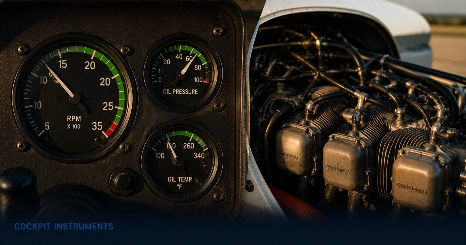
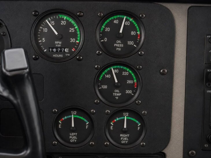
In a single-engine light aircraft, the engine instruments are typically grouped together on the right side of the instrument panel or on a centre console between the pilot and co-pilot positions. The exact set varies significantly by aircraft type and age. A basic training aircraft such as a Cessna 172 carries a tachometer, oil pressure gauge, oil temperature gauge, and fuel quantity gauges as the core set. A more complex piston aircraft — one with a constant-speed propeller and a higher-performance engine — adds a manifold pressure gauge, exhaust gas temperature probe, and cylinder head temperature gauge. Together, these instruments give the pilot a continuous picture of the engine’s health and output.
The tachometer
The tachometer shows engine speed in revolutions per minute (RPM) and is the primary power indicator on any aircraft with a fixed-pitch propeller. The face is a simple dial with a green arc marking the normal operating range and a red line at the maximum permitted RPM. In a Cessna 172, the green arc runs from 2,100 to 2,700 RPM, with the red line at 2,700. For takeoff and climb, the pilot typically applies full throttle and allows the engine to reach its maximum rated RPM. For cruise, the throttle is reduced to a setting that produces an RPM in the middle of the green arc, balancing power and engine wear. Operating above the red line risks mechanical damage; operating consistently below the green arc means the engine is underloaded and may foul spark plugs over time.
The manifold pressure gauge
The manifold pressure (MP) gauge is found only on aircraft fitted with constant-speed propellers. On these aircraft, the pilot has two power controls: the throttle, which controls the volume of air and fuel entering the engine and is read on the manifold pressure gauge in inches of mercury (inHg), and the propeller control, which sets the RPM independently. With both controls, the pilot can set precise power combinations — a typical cruise setting might be 23 inches of manifold pressure at 2,300 RPM, which together correspond to a known percentage of engine power. When the engine is not running, the manifold pressure gauge reads ambient atmospheric pressure, typically around 29 to 30 inHg at sea level. As the throttle is reduced, the reading drops. One important quirk: at a constant throttle setting, manifold pressure rises as the aircraft descends into denser air. Pilots must monitor the MP gauge during descent and reduce throttle gradually to prevent the engine from being overloaded.
The oil pressure gauge
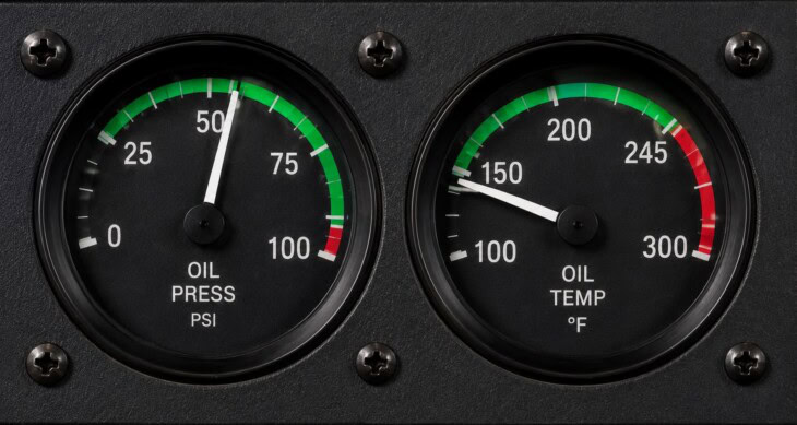
The oil pressure gauge is the most critical engine instrument in a piston aircraft. It monitors the pressure at which the engine’s lubrication system is circulating oil through the bearings, cylinders, and moving parts. Without adequate oil pressure, metal surfaces make direct contact, generate heat, and can seize within seconds to minutes. In a Cessna 172, the normal operating range is 60 to 90 PSI (green arc), with a low red line at 25 PSI and a high red line at 100 PSI. After engine start, oil pressure should rise to the green arc within 30 seconds in normal temperatures; in cold weather, it may take slightly longer. A pilot who does not see oil pressure by the time 30 seconds have passed shuts the engine down and investigates before continuing.
A drop in oil pressure during flight requires immediate action. The pilot reduces power to reduce the load on the engine, declares an emergency, and begins planning for a landing as soon as possible. Unlike some other abnormal readings that allow time to monitor and assess, low oil pressure is treated as a potential precursor to imminent engine failure. An engine that loses oil pressure can seize without further warning. Pilots are taught to treat a falling oil pressure gauge the way a surgeon treats a falling heart rate: act before the problem becomes irreversible.
Engine instrument priority
Oil pressure is the most urgent instrument. A drop toward the red line demands immediate action — reduced power and a plan for landing. Oil temperature works in tandem with oil pressure; high temperature combined with dropping pressure is more serious than either alone. The tachometer confirms power output. Fuel gauges are the least reliable instrument on the panel and should never be the sole basis for a fuel decision.
The oil temperature gauge
The oil temperature gauge shows how hot the engine oil has become. Oil serves both as a lubricant and as a cooling medium, absorbing heat from the engine and releasing it through the oil cooler. Normal oil temperatures vary by aircraft type and engine, but most piston aircraft have a green arc covering the normal operating range and red lines at high and low extremes. A cold oil temperature at engine start is expected and normal; pilots allow the engine to warm up to the green arc before applying full power for takeoff. Running a cold engine at full power before the oil has reached operating temperature risks damage to components that depend on properly viscous oil for lubrication.
High oil temperature in flight may indicate low oil quantity, a blocked oil cooler, an excessively rich mixture, or sustained operation at high power in hot ambient conditions. It should be interpreted together with the oil pressure gauge: high temperature alongside normal pressure may indicate an overheat that can be managed; high temperature alongside falling pressure is a more urgent combined failure that suggests the engine is losing oil and must be treated as an emergency. In many light aircraft the two gauges are mounted side by side for exactly this reason.
Fuel quantity gauges
Most light aircraft have separate fuel quantity gauges for the left and right wing tanks, showing the quantity of fuel remaining in each tank — typically in US gallons or fractions of a full tank. These gauges are the least reliable instruments on the panel. FAA certification rules require fuel gauges to be accurate only when they read empty; any reading other than empty carries no guaranteed accuracy. Float sensors can stick, fuel transmitters corrode, and temperature changes affect readings. A gauge showing a quarter tank could represent anything from nearly empty to a legitimate quarter tank, depending on the state of the sensor.
Why pilots do not trust the fuel gauges alone
The NTSB identified fuel mismanagement as one of the top causes of general aviation accidents, with roughly fifty fuel exhaustion events each year — almost all preventable. In many cases, pilots trusted gauge readings that were inaccurate. Correct fuel management in a piston aircraft requires three things: a visual check of the tanks before every flight (dipping or looking directly into the filler neck), tracking actual fuel burn against time and power setting in the air, and planning with a known reserve. The gauges provide a useful cross-check, but they are never the primary fuel accounting method.
Exhaust gas temperature and cylinder head temperature
The exhaust gas temperature (EGT) gauge and cylinder head temperature (CHT) gauge are more commonly found in complex piston aircraft than in basic trainers. The EGT probe sits in the exhaust system and measures how hot the gases leaving the cylinder are — a reading that changes predictably as the pilot adjusts the fuel-air mixture. Pilots use the EGT gauge to lean the mixture in cruise: reducing the fuel supply until the EGT reaches its peak reading, then adjusting to the desired lean or rich-of-peak position for fuel economy or engine cooling purposes. Leaning correctly can extend range significantly on a long cross-country flight; leaning incorrectly, or failing to lean at all at altitude, burns unnecessary fuel and can cause spark plug fouling.
The CHT gauge measures the temperature of the cylinder head itself, which is the best single indicator of how much thermal stress the engine is experiencing. High CHT — sustained above roughly 400°F in many piston engines — risks detonation, where fuel in the cylinder ignites prematurely, and can cause permanent engine damage. CHT rises when the mixture is too lean around the peak EGT zone, when the aircraft is climbing at high power in hot conditions, or when cowl flaps are closed in circumstances that restrict engine cooling airflow. Managing CHT means watching it during climb and enriching the mixture or reducing power if temperatures approach the warning range.
When a gauge goes into the red
The foundation of effective engine monitoring is knowing what the gauges look like on a normal flight. A pilot who has flown the same aircraft fifty times knows exactly where the oil pressure needle sits in cruise, what the tachometer reads at 2,300 RPM, and how the fuel gauges behave after an hour of flight. This baseline makes abnormalities obvious: a needle that has moved is immediately noticed because it is not where it always is. A pilot who does not know their aircraft’s normal readings has to evaluate whether a reading is abnormal from first principles every time they scan the panel, which is slower and less reliable.
When a gauge does enter the red, pilots are trained to distinguish between two levels of response. The instruction to “land as soon as possible” means exactly that: get on the ground at the nearest suitable airfield without delay, declare an emergency with ATC, and prioritise landing over all other considerations. This response applies to imminent threats — dropping oil pressure, unusual engine noises combined with gauge abnormalities, or smoke from the engine. The instruction to “land as soon as practical” applies to less acute situations: a gauge reading that is slightly outside normal range but stable, or a caution-level warning that does not suggest immediate failure. The pilot selects a suitable airport within reasonable range, informs ATC, and plans an orderly arrival rather than treating it as an immediate emergency.
In both cases, the rule is the same: do not ignore an abnormal gauge and hope it resolves itself. Engine problems in light aircraft that are caught early — a pressure drop still within manageable range, a temperature reading that is rising but not yet at the limit — can often be managed to a successful landing. The same problems ignored for another ten minutes of flight can result in an engine that stops without further warning. The gauges exist precisely to give pilots time to act.
Engine instruments in a glass cockpit
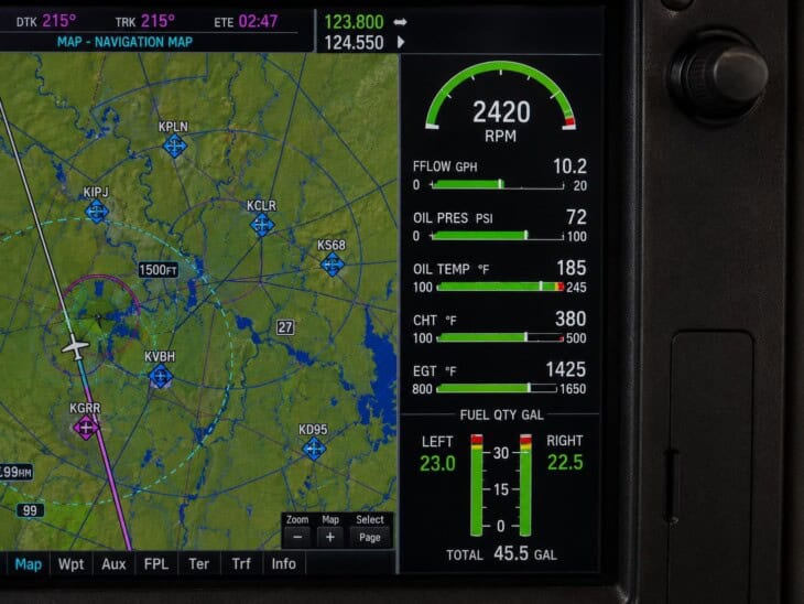
In glass cockpit aircraft such as those equipped with the Garmin G1000, the individual analogue engine gauges are replaced by an Engine Indication System (EIS) — a dedicated page on the Multi-Function Display that presents all engine parameters digitally in a single, compact layout. RPM, manifold pressure, oil pressure, oil temperature, CHT, EGT, and fuel quantity all appear as a column of digital readouts and graphic indicators on the right side of the MFD. Colour coding replaces the green and red arcs of the analogue gauges: readings in the normal range display in white or green, caution ranges in yellow, and limit violations in red. The system can alert the pilot automatically when any parameter reaches a caution or warning threshold, which means an out-of-range reading triggers a visual alert even if the pilot is not looking at the EIS page at that moment.
In commercial aviation, the equivalent systems are far more extensive. Boeing aircraft use the Engine Indicating and Crew Alerting System (EICAS), which monitors engine performance, hydraulic systems, fuel, electrical systems, and pressurisation across the entire aircraft, presenting alerts to the crew in a prioritised format. Airbus aircraft use the Electronic Centralised Aircraft Monitor (ECAM), which performs the same function with a slightly different philosophy: ECAM not only alerts the crew to failures but displays the relevant checklist actions directly on screen. Both systems represent the same fundamental principle as the analogue oil pressure gauge in a Cessna 172 — giving the pilots visibility into what the engine and aircraft systems are doing — scaled to the complexity of aircraft with multiple engines, redundant hydraulic systems, and automated monitoring requirements that far exceed what any manual instrument scan could provide.
For the full picture of how a glass cockpit replaces the six-pack flight instruments and integrates navigation, weather, and engine data into a unified system, see Glass Cockpit Explained. For an overview of how all cockpit instruments — flight instruments and engine instruments — fit together in a complete panel, see Airplane Cockpit Instruments Explained.
FAQ
Get the Newsletter
The latest aviation news and stories sent to your inbox.
About the Author

Tim is the owner and lead editor of AeroCorner since 2019, overseeing aviation content covering aircraft, airlines, airports, and the broader aviation industry. Through years of researching, writing, editing, and publishing aviation-focused content, he has developed extensive practical knowledge of commercial aviation and air travel. Based in Asia and a frequent traveler himself, Tim also brings firsthand passenger experience to AeroCorner’s coverage. Outside of publishing, he has also explored aviation firsthand through hands-on flight training in New Zealand.